Table of Contents
After choosing the glass or crystal that you intend to use, find the proportion, which serves as a measure for its refractions.
This can be conveniently found with the help of such an instrument.
EFI is a completely flat and straight board or ruler made of a not too shiny nor transparent material. The light striking it should be easily distinguished from the shadow.
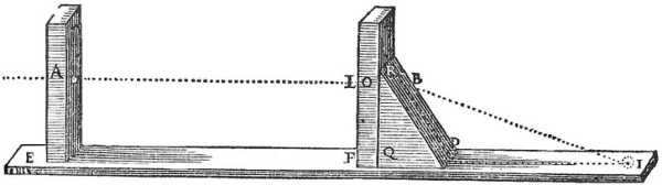
EA and FL are 2 small blades that are not transparent. These are raised perpendicular to EFI.
It has 2 small round holes, A and L, placed exactly opposite each other.
The ray AL passes through is parallel to the line EF.
Then RPQ is a piece of the glass you wish to test. Cut in into a triangle, of which:
- the angle
RQPis right PRQis more acute thanRPQ.
The 3 sides RQ, QP, and RP are 3 completely flat and polished faces.
The face QP is pressed against the board EFI, and the other face QR against the blade FL.
The sun’s ray passes through the two holes A and L penetrating as far as B through the glass PQR without suffering any refraction. This is because it meets its surface RQ perpendicularly.
But having reached the point B where it meets its other surface RP obliquely, it cannot emerge without bending towards some point on the board EF, as for example towards I.
This instrument makes the sun’s ray pass through these holes A and L, in order to know the ratio that the point I (the center of the small oval of light that this ray describes on the board EFI) has with the 2 other points B and P.
Bis the one where the straight line passing through the centers of the two holesAandLterminates on the surface RP;Pis the one where this surfaceRPand that of the boardEFIare cut, by the plane that is imagined to pass through the points B and I, and also through the centers of the two holes A and L.
Transfer the triangle BPI with a compass onto paper.
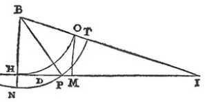
From the center B, draw the circle NPT through the point P. Having taken the arc NP equal to PT, draw the straight line BN which cuts IP extended at the point H.
Then again from the center B through H, draw the circle HO which cuts BI at the point O.
You now have the proportion between the lines HI and OI as the common measure of all the refractions that can be caused by the difference between the air and the glass you are examining.
If after that, on the straight line HI, you take MI equal to OI, and HD equal to DM, you will have D for the summit, and H and I for the burning points of the hyperbola.
You can make these 3 points HDI more or less distant than they are, simply by drawing another straight line parallel to HI farther or closer to the point B. Drawing 3 straight lines BH, BD, BI from this point B that cut it.
There is the same ratio between the three points HDI and hdi, as between the three HDI.
Having these 3 points, you can trace the hyperbola by planting 2 pegs at the points H and I, and making the cord placed around the peg H be so attached to the ruler that it cannot fold back towards I, farther than up to D.
If you prefer to trace it with the ordinary compass by finding several points through which it passes; place one of the points of this compass at point H.

Open it so that its other point passes a little beyond point D, as far as I, from the center H.
Draw the circle I33. Then make M2 equal to HI from the center I through point 2.
Draw the circle 233 which cuts the previous one at the points 33, through which this hyperbola must pass, as well as through the point D, which is its summit.
Then put the point of the compass back at the point H. Open it so that its other point passes a little beyond the point I, as far as 4. From the center H draw the circle 466.
Take M5 as equal to H4 from the center I through 5. Then draw the circle 566 which cuts the previous one at the points 66 which are in the hyperbola.
Continue to place the compass point at point H. The rest as before, you can find as many points as you please of this hyperbola.
This may not be bad for roughly making some model that roughly represents the shape of the lenses to be cut.
But to give them this figure exactly, it is necessary to have some other invention by means of which one can describe hyperbolas in one stroke, as one describes circles with a compass.
First, from the center T, which is the middle of the line HI, draw the circle HVI.
Then from the point D raise a perpendicular on HI which cuts this circle at the point V.
Draw a straight line from T through this point V. You will get the angle HTV.
Imagine it rotating around the axis HT so that the line TV will draw the surface of a Cone.
On that surface, the section made by the plane VX parallel to this axis HT, and on which DV falls at right angles, will be a hyperbola exactly similar and equal to the previous one.
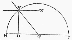
All the other planes parallel to this one will also cut in this Cone hyperbolas all similarly but unequally.
They will have their foci more or less distant according as these planes are distant from this axis.
After which one can make such a machine.
Leave a Comment
Thank you for your comment!
It will appear after review.